Definitions
Standard to determine the heat storage capacity of PCM using hf-DSC with constant heating/cooling rate (dynamic mode) - Task 4229 PCM DSC procedure
Introduction
The measurement procedure defined in this document is based on the already existing standard RAL-GZ 896 page (www.PCM-RAL.de). The T4229 is extending the procedure for PCM-characterization using DSCs by:
- Definition for the calibration of the DSC
- Definitions/suggestion for the sample preparation
- Detailed description for the measurement
- Suggestion for the improvement of the measurement results (analyzes/evaluation)
Main Objectives
Scope of the IEA task 42 / Annex 29 Standard
This standard is valid for the determination of the heat storage capacity of PCM using hf-DSC with constant heating / cooling rate (dynamic mode) (Modulated or stepwise is not considered)It gives additional guidelines and comments, specifically for using hf-DSC with constant heating / cooling rate (dynamic mode) on topics not treated or not treated in detail by the RAL-GZ 896 standard.
General remarks
- The sample for measurement must be representative
- Ensure there is no reaction between sample and crucible
- This procedure is not valid for samples showing degradation during the measurements
Procedure
Number of samples and measurements
At least 3 samples per product should be investigated. At least one measurement must be carried out per sample (consisting of 4 cycles each (heating and cooling ramp) over the temperature range of the complete phase transition).
Sample preparation
Use typical sample mass:
- e.g. 10mg in hf-DSC(perform all measurements, heating rate test and sample measurements, with similar masses. Deviations of sample masses should be less than ±20%)
- crucible must be filled less than 2/3rd ( 1/3rd gas volume for thermal expansion of the sample)
- sample should cover bottom surface
- resulting hf-signal must be within device resolution
- good noise to signal ratio should be obtained
- The crucible should be closed (e.g. cold welded) if possible to avoid material losses or absorptions
Temperature range determination if phase transition temperature range is unknown do first scan with less than 10 K/min heating and cooling rates including the whole assumed melting and crystallization range with respect to material temperature limitations
- determine required temperature range
- full melting and crystallization must be included (Always perform full cycles including heating and cooling measurements), but not beyond material limits (The temperature range must be selected, taking the manufacturer’s data into account, such that the sample is not damaged; according RAL)
- heating rate must be constant during melting and crystallization (transient oscillation when going from isothermal to ramp or reverse must be considered)
Heating rate determination - Process to ensure thermal balance / thermal equilibrium
- perform a heating rate test (according RAL GZ 896)
- slow down the heating and cooling rate by halve from one full cycle to the next
- use typical heating rates for your device, e.g. hf-DSC: 4, 2, 1, 0.5, 0.25 K/min
- slow down the heating and cooling rate by halve from one full cycle to the next
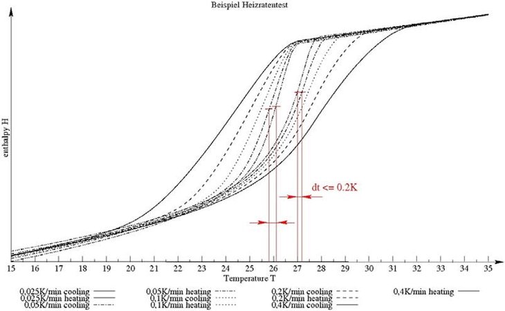
- determine inflection points temperature of enthalpy plots, or peak temperature of heat flow signals (Figure 1)
- if the difference between inflection point or peak-temperature (from one heating and cooling ramp to the next slower one) is less than 0.2 K choose the slower one (Figure 2)
- if the cooling ramp cannot be analyzed (e.g. loop behavior of heat flow signal because of subcooling) then it is sufficient to just consider heating ramps
- if the difference between inflection point or peak-temperature (from one heating and cooling ramp to the next slower one) is less than 0.2 K choose the slower one (Figure 2)
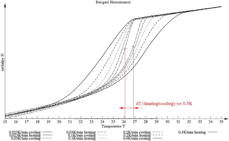
- or if the temperature difference of the inflection points of heating and cooling is less than 0.5 K (Figure 2)
- determine temperature range for following measurement
- use heating rate resulting from heating rate test
- select temperature range ensuring the whole phase transition is included
Calibration
- temperature calibration:
- perform calibration with determined heating rate
- select at least 3 calibration substances covering the desired temperature range
- e.g. Water, Gallium, Indium
- heat flow signal during calibration should be in the range of those measured with the sample
- set general temperature correction
- enthalpy calibration: (if not done using temperature calibration standards)
- perform calibration with determined temperature range
- select calibration substances covering the desired temperature range
- set general enthalpy correction
Measurement
- Perform at least 3 different sample measurements of the same substance
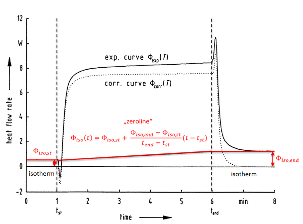
- Use isothermal periods before and after each cooling/heating period to reach the thermal equilibrium and assure that DSC signal remains to be constant (Always ensure to reach thermal equilibrium in isothermal sections of the measurements for baseline construction according ASTM (Figure 4) and consider slow crystallization)
- Measure all empty crucibles (with lid laid on it)
- Use determined heating/cooling rates, use temperature limits and duration of isothermals chosen for the sample measurement, apply one cycle,
- Apply sample and close crucible
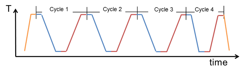
- Apply three measurement cycles
- Use determined heating/cooling rates, apply cycle1 to 3 according to, use sample isothermals according to Figure 3
- Apply one fast cycle (cycle 4) at the end of one of the measurements to check the enthalpy at higher heating rates (e.g. 4 x determined heating rate, better signal to noise ratio)
Analysis
- Substract “zeroline” from blank and sample measurement for each cycle if the heat flow signal is not 0 at the end of the isotherms [1] (verify thermal equilibrium, see 2.7)
- Substract blank (empty crucible measurement) from sample measurement for each sample and each cycle
- Calculate the mean value and standard deviation of the 3 measurements (cycle 1 – 3) for onset, offset, peak temperature and heat of fusion as well as heat of crystallization
- Calculate the enthalpy curves
- Choose a temperature above Toffset melting-peak (sample should be completely molten + e.g. 1 – 3 K) as reference and set enthalpy at this temperature to 0J/g
Content of the test result
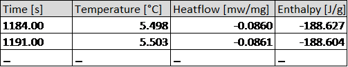
Export the data of the first 3 cycles of each sample measurement (for heating and cooling) in ASCII-format. Data file must contain the columns in the order 1. Time [s], 2. Temperature [°C], 3. heatflow [mW/mg], 4. Enthalpy [J/g] (Table 1)
Table 1: Format od data file
Upload the data for all 3 samples to www.thermalmaterials.ise.fraunhofer.de